|
Fuel intake / injectors / hoses removal
& overall Page
1- 2
|
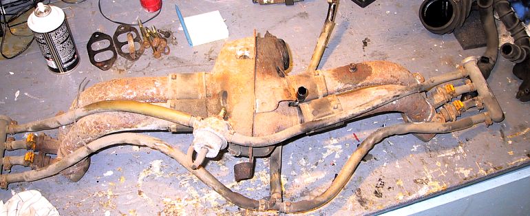
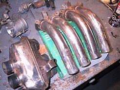
This is
my “very rusted & dirty” intake system (you know now why it’s out!!!,
(originally I just wanted to change all fuel hoses…).
The following
picture will show how to replace the injectors O-ring / seals,
understanding and checking the throttle body switch and removing &
painting the main body and parts.
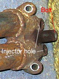 |
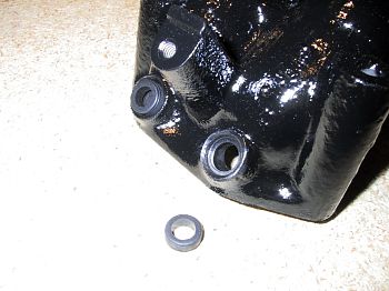
The
injectors are attach to the body by a single screw (Bolt) true an
holding plate in the center. Remove the screws and slowly pull
both injectors at the same time. Each injectors are seal by a
small o-ring. (see picture below for more info) |
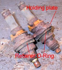 |
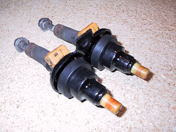
The 2 big
O-ring are inserted in a groove in the center of each injectors,
when the holding plate is screwed to the body, the big O-rings are
compress and hold the injectors in place. The 2 small one seal the
injectors to the body. |
|
|
The intake housing before sanding. (sand
with a rotating steel brush & rotating sanding disk)
|
Sanded and polish, ready for painting.
|
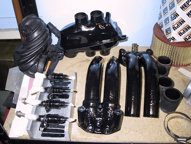 |
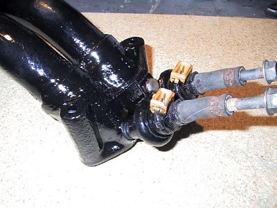
Every part cleaned and painted, even the
injectors. Paint use was high quality engine paint (fuel & heatproof). |
|
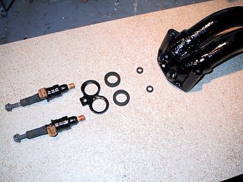
Injectors after cleaning & painting, the 2
new big retainer O-ring are in with the plate.
|
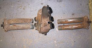
Here you can see all parts & installing
steps.
|
New paint had to be remove from injectors
holes with a Dremel or any high speed brush before putting back the
new O-Ring. Note: I am thinking of applying a
small coat of Loctite
around each injectors small O-Ring to make sure that there is no air
coming from there. |
Final assembly, Locktite on the single
screw is a must for safety. |
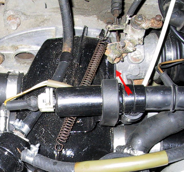
Throttle Switch assembly
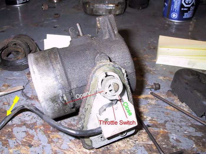
The throttle switch give 2 distinct signal to the ECU (FI computer), one at idle and
one at full throttle. She need to be perfectly align with the metal bump
of the switch, she as 2 position (plastic lips / bump); fully close (On) &
fully open (On), in between she is close. 2 Allen’s screws can be move to
align the switch. This should be OK because it is improbable that she
moved. To check if the switch is “Electrically” OK, take a volt / ohm
meter and put it at the continuity check position, touch each tab of the
connector (follow the yellow arrow until you find the connector) and play
with the throttle body by opening this one the fully open position and the
fully close position, you should here a “bip” or read “0” on the
voltmeter.
Back |