Installation of the Vanaru cooling system, fuel line and gas cable/ wire for
FBW gas pedal.
Installation du kit de refroidissement Vanaru, des
lignes a essence et de câble a gaz / pédale électronique

|
The fuel pressure system and the operation of the gas
cable / electronic actuation of the throttle body
Le système de control des gaz (par câble ou électronique) et le système de
pression d'essence.
|
|
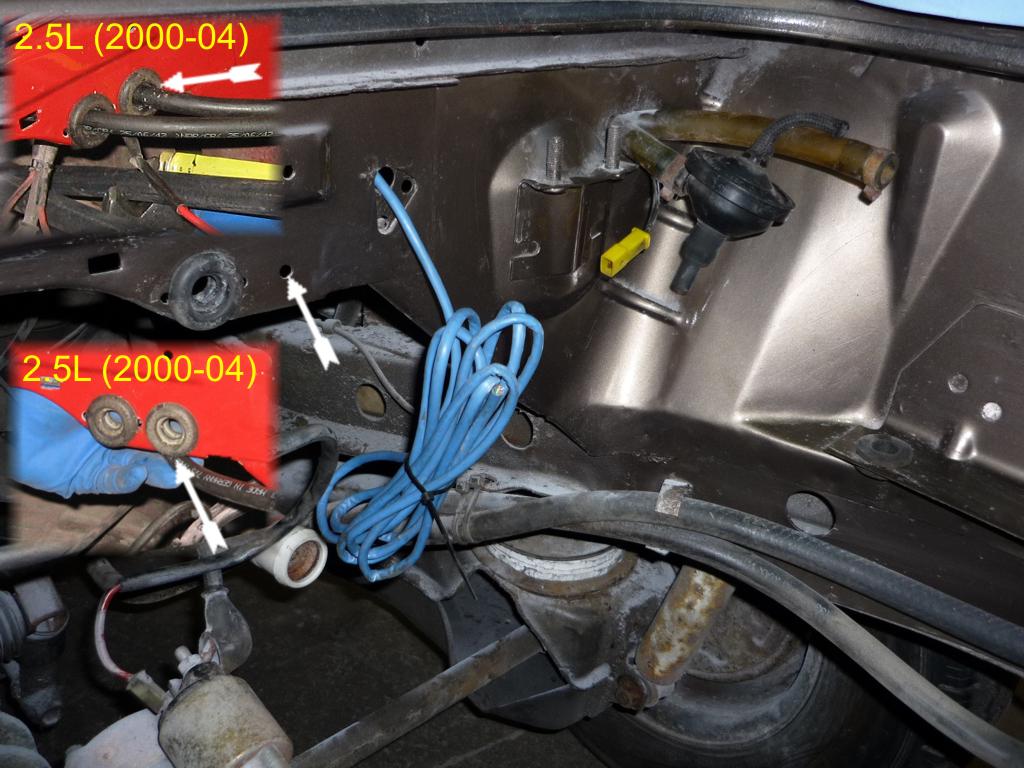
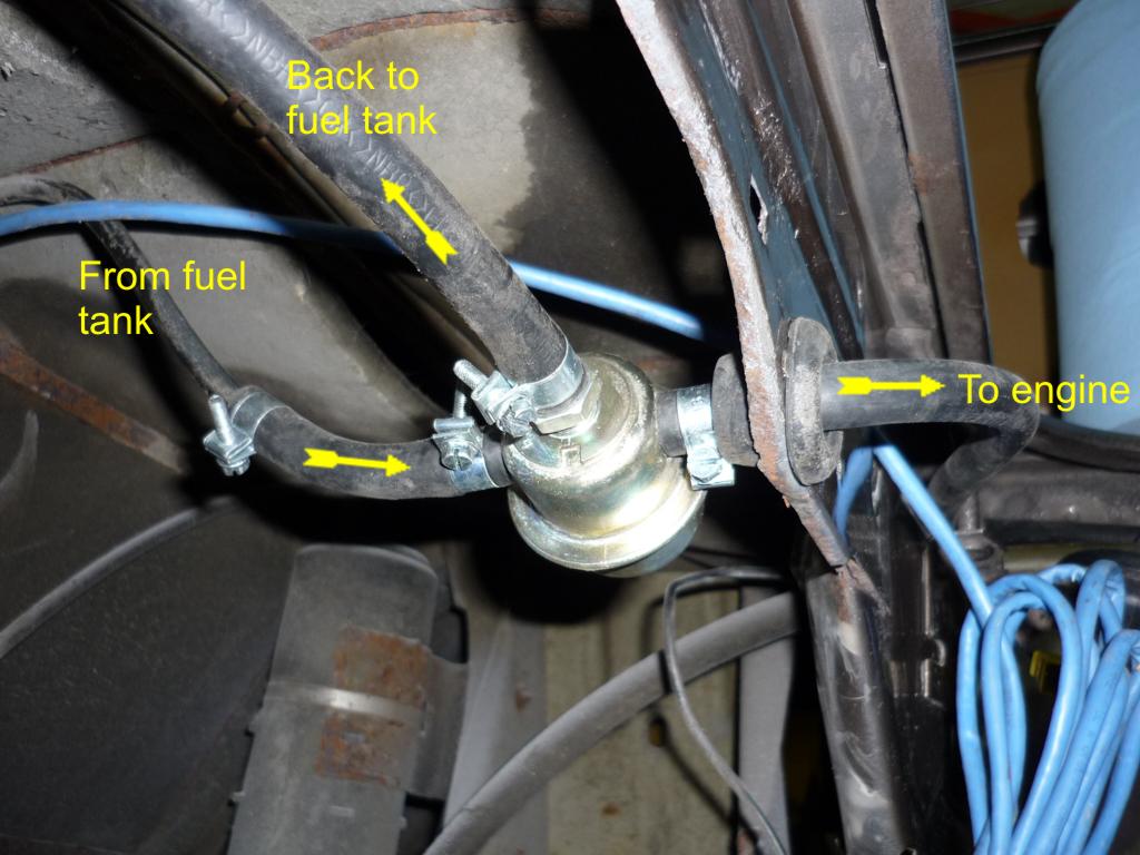
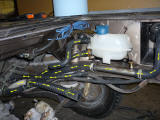
On 2000-2004 engine the fuel pressure system is standard (fuel pressure
regulator on the engine). It mean there is a line comming from the fuel pump
and a line going back (surplus/overflow) to the tank. In that case, a
second hole need to be drilled beside the original one (see red images) to
have a line going to the engine and a line comming back from the engine and
going to the tank. |
On later engine (2005-07), the fuel pressure regulator is before the the
engine (in the tank on a Subaru car). So only the original line is needed
with the addition of a gromet. |
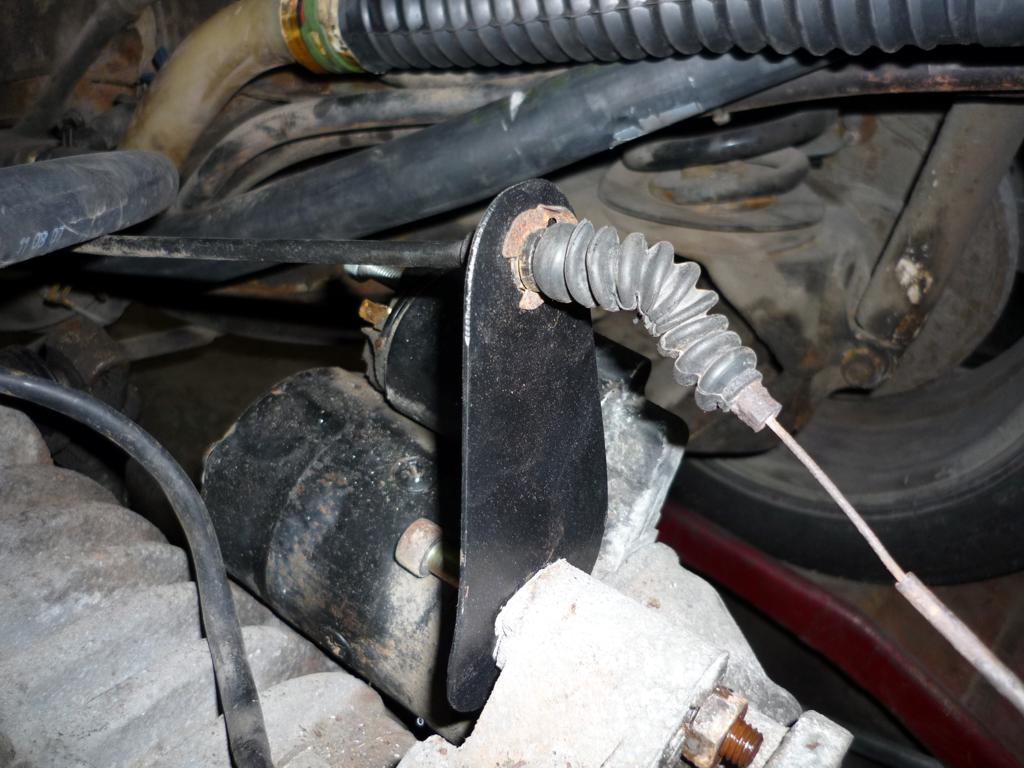
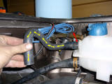
On 2000-2004 engine, the throttle body/gas pedal is a standard butterfly,
it's activated with a cable, a new cable bracket is then installed (picture
bellow. On later (05-07) engine (Blue shielded network cable-picture on the
left), the throttle body/butterfly is electronic (Fly By Wire) The use of
the Subaru gas pedal and a shielded wire is needed. |
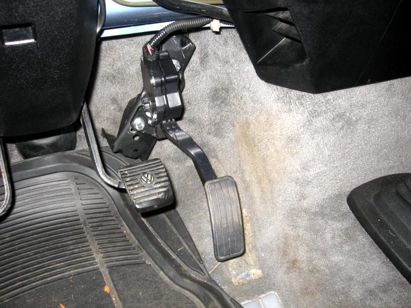
The Subaru gas pedal |
|
 |
 |
 |
 |
|
| Sur les moteurs
2000-2004 le system de pression d'essence est standard, c'est a dire que le
moteur a besoins d'une ligne d'entrer venant de la pompe a essence et d'une
ligne de surplus/retour d'essence qui se dirige vers le réservoir. Dans ce
cas, un deuxième trou doit être percé a coté (droite) du trou d'origine afin
que les deux ligne passe a travers le mur. |
Sur les moteurs
plus récents, le system est plus moderne et la régulation de l'essence se
fait avant le moteur, dans ce cas, seulement le trou d'origine est
nécessaire. Le régulateur (dans le réservoir sur une voiture Subaru) est
placé de l'autre coté du mur. |
Sur les moteurs
2000-2004, un câble a gaz relis la pédale des gaz au "Throttle body" /
papillon des gaz situé a l'arrière sur le moteur. Dans ce cas, un nouveau
support est installé pour soutenir le câble a la bonne position. Sur les
moteur plus récents (2005-2007), il n'y a plus de câble a gaz (Fly By Wire),
le papillon des gaz est activer électroniquement par l'intermédiaire d'une
pédale électronique (venant de la voiture Subaru) et d'un fils de réseau
protégé (Shielded) (câble bleu sur la photo de gauche) |
Installation de la
pédale a gaz Subaru |
|
|
Installation of the Vanaru cooling system
Installation du système de refroidissement Vanaru
|
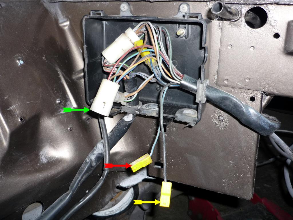
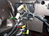
This is what is left in the junction box after the main VW harness is gone.
Yellow: Ignition
Red: Alternator
Green / Main plug: start signal, engine temp, oil pressure, RPM,
coolant level... |
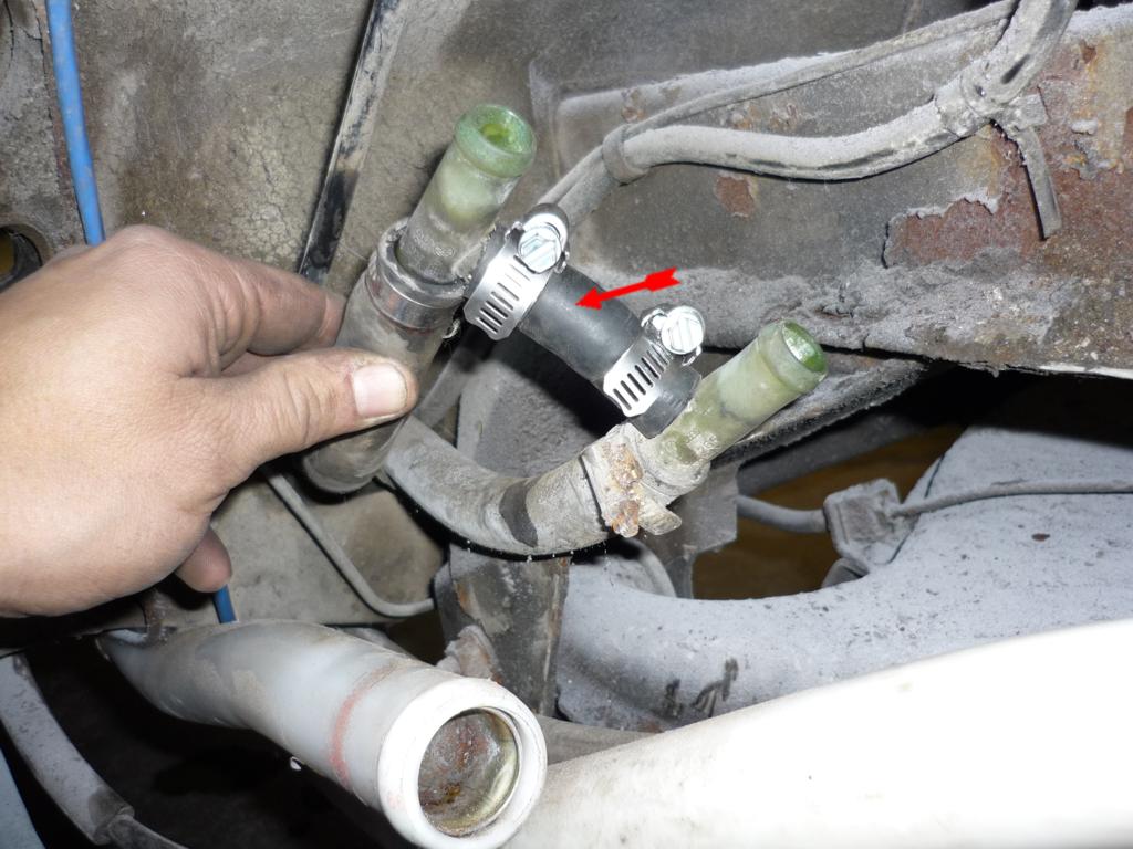
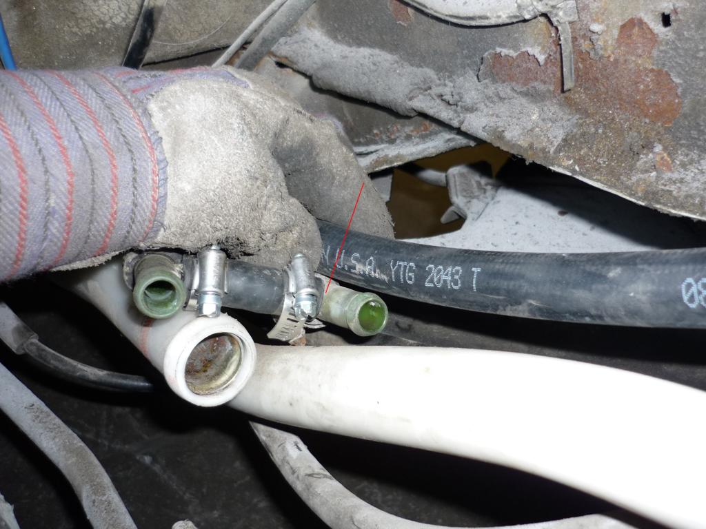
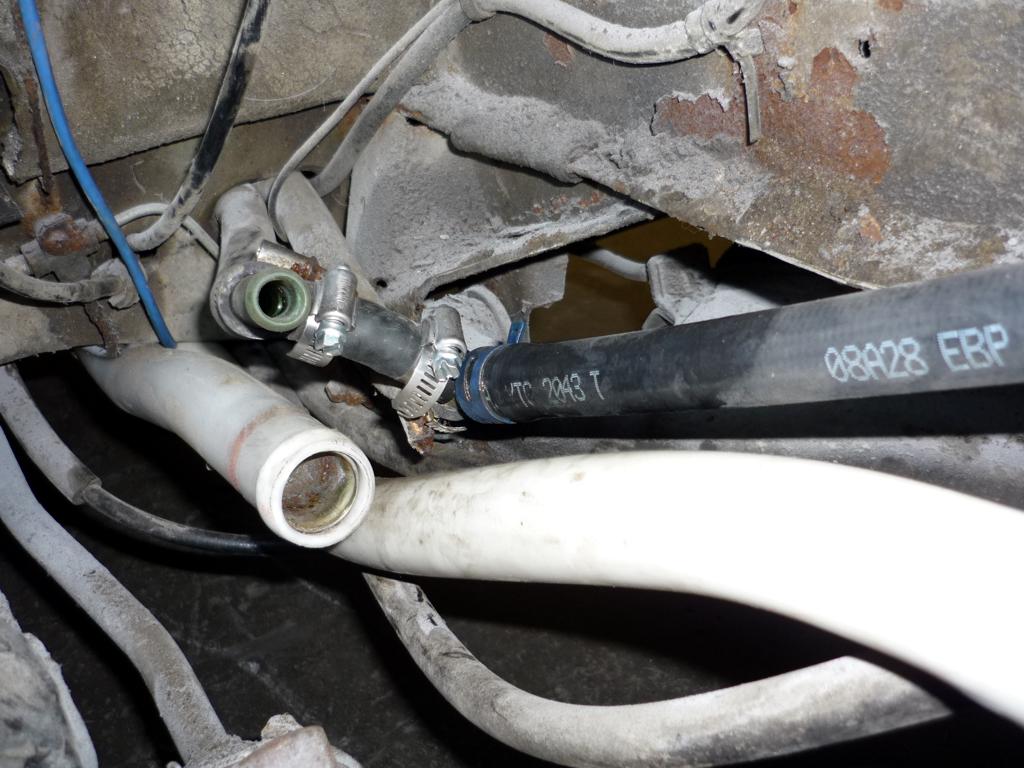
Here are the 2 new main coolant line (86+) installed on a 85. You can also
see the 2 heaters line with the "T" junction on each one (on a van with a
rear heater, those would stay stock (not join together). If a rear heater is
present, remember that this one NEED to say open (hot) all the time), in
that case, the rear heater as been remove. Still, it is a must (safer) that
the 2 heater line are joined together to give a better information about the
temperature of the engine to the thermostat. |
The junction |
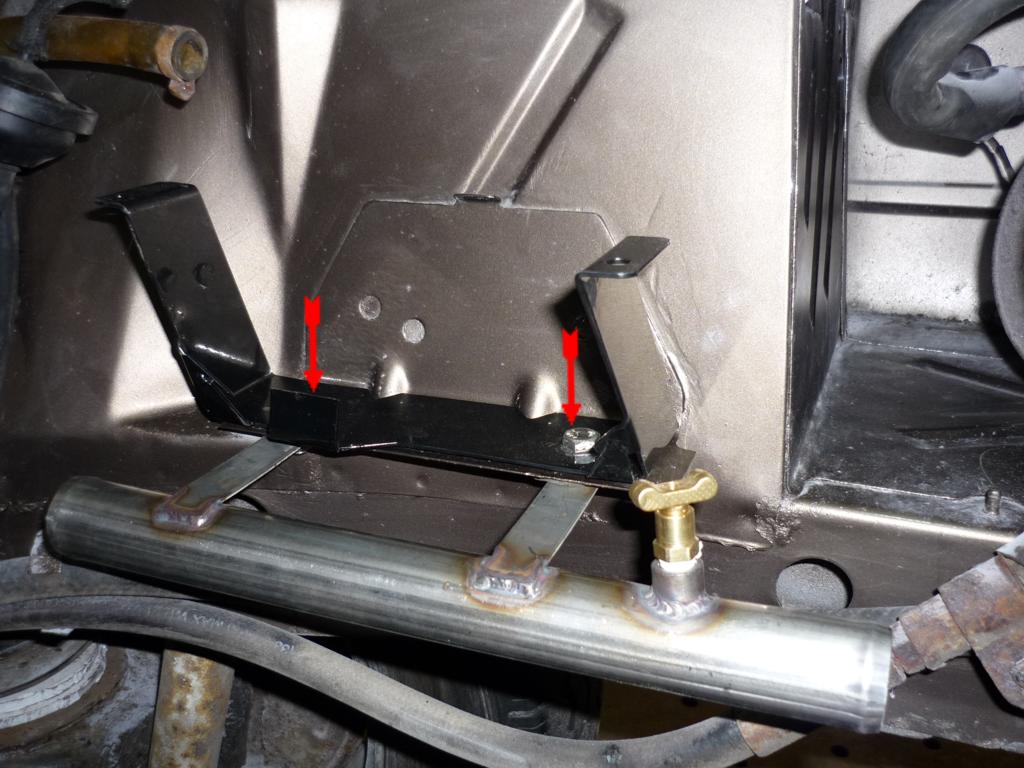
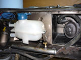
Installation of the coolant tank bracket (in black) and the coolant return
tube with bleeder screw. Just use the 2 hole that where use to hold the old
filter box. |
Installation of the EXP tank |
 |
 |
 |
 |
 |
Voici ce qui reste
dans la boite de jonction apres que le harnais VW est enlevé.
Jaune: Ignition
Rouge: Alternateur
Vert / connecteur principal: Signal de démarrage, temp. moteur,
pression d'huile, RPM, niveau de liquide refroidissant... |
Voici les deux
nouvelles ligne (1986+) principale de refroidissement installé sur un 85. En
arrière, on vois les deux lignes de chaufferette avec leurs jonctions en
"T". Dans ce cas, la chaufferette arrière a été enlevé donc nous allons
joindre les deux ligne pour que le thermostat soit mieux informé de la
température du moteur. Dans le cas ou la chaufferette arrière est présente,
il faut simplement s'assurer que celle ci est en position "Chaude" en tout
temps. |
La jonction |
Installation du
support du réservoir de liquide refroidissant (Exp. Tank) et du tube de
retour avec vis de purge du système. Utiliser les deux trous de support de
l'ancienne boite du filtre a air |
Installation du
réservoir d'expansion. |
|
|
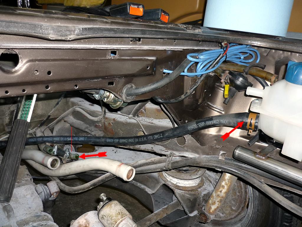
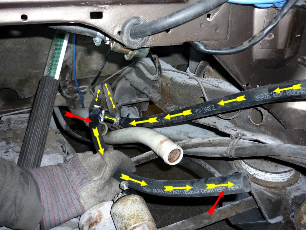
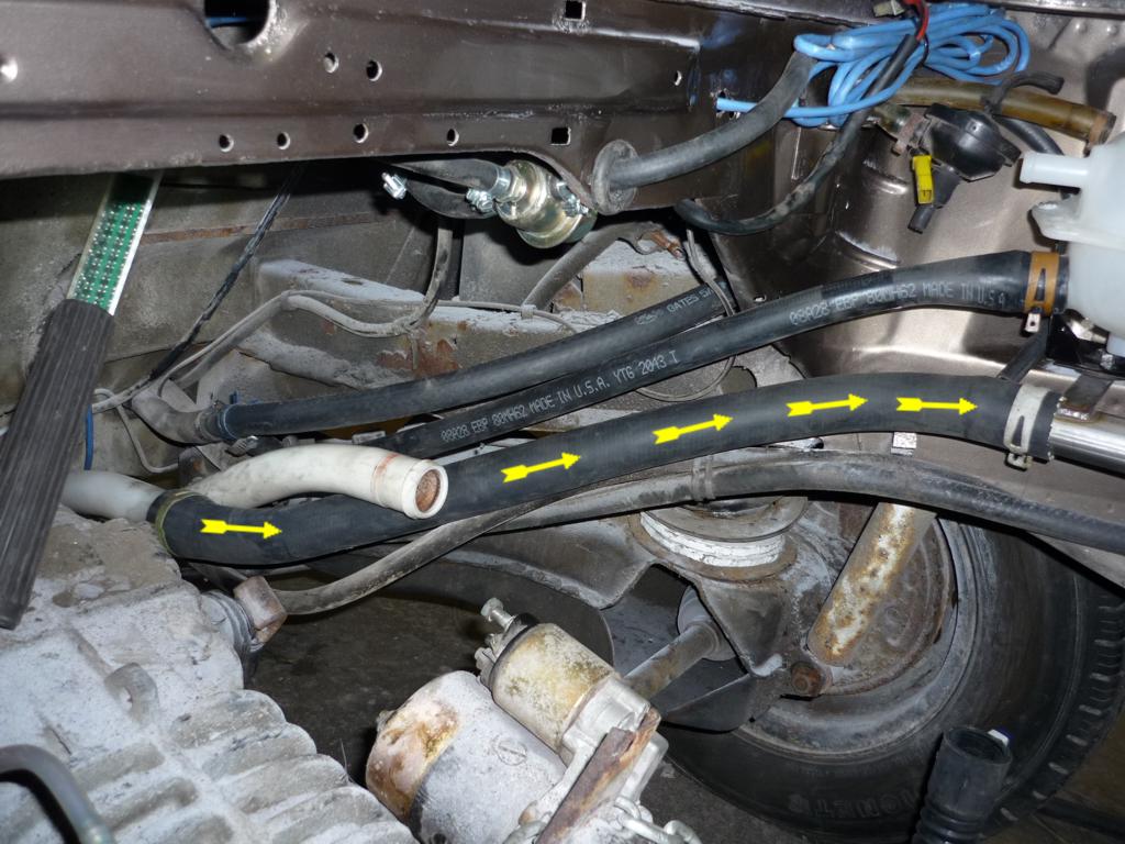
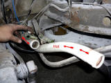
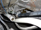
Here is the first hose to
install (outgoing hot coolant from EX tank to heaters hose), it as a bigger
end near the EX tank, this one also need to be cut to the right length. We
use OEM VW clamp when possible, it is not a must to do so, normal (good
quality) hose clamp can be use. |
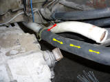
Installation the the return
heater line. 2 feet of 5/8 heater line, this one will be cut later near
engine. The arrows also show the coolant flow. |
   |
 |
| Voici
la premier tuyau flexible à installer (ligne de liquide chaud allant aune
des deux ligne de chaufferette). Elle à un plus gros diamètre du coté du
réservoir. Il faut aussi couper celle ci près de la jonction en "T". Nous
utilisons des bagues d'origine VW, mais des bagues normales de qualité
preuves aussi êtres utilisé en toute confiance. |
Installation de la ligne de retour de liquide provenant des chaufferette(s).
Une ligne standard de 5/8 de deux pieds. La photo montre aussi la
circulation du liquide. |
|
|
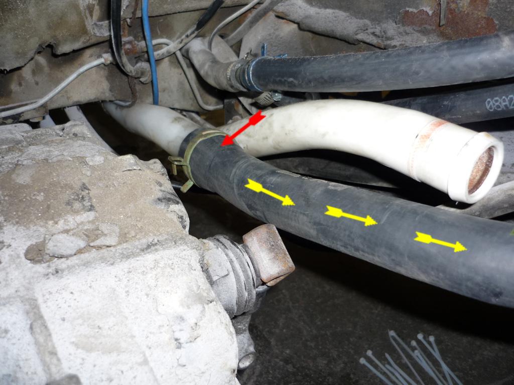
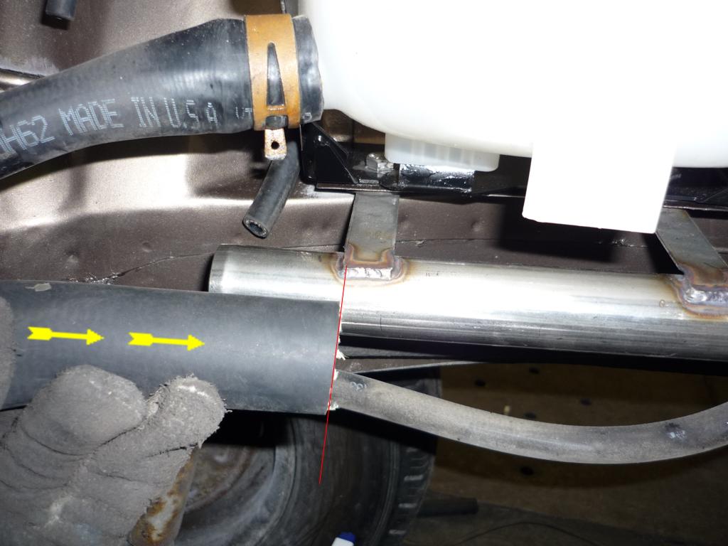
Installation of the main coolant
return line. This one need also to be cut to the right lenght. It will/should
cross under the other main one. It's also bigger in diameter on the white
plastic pipe side. |
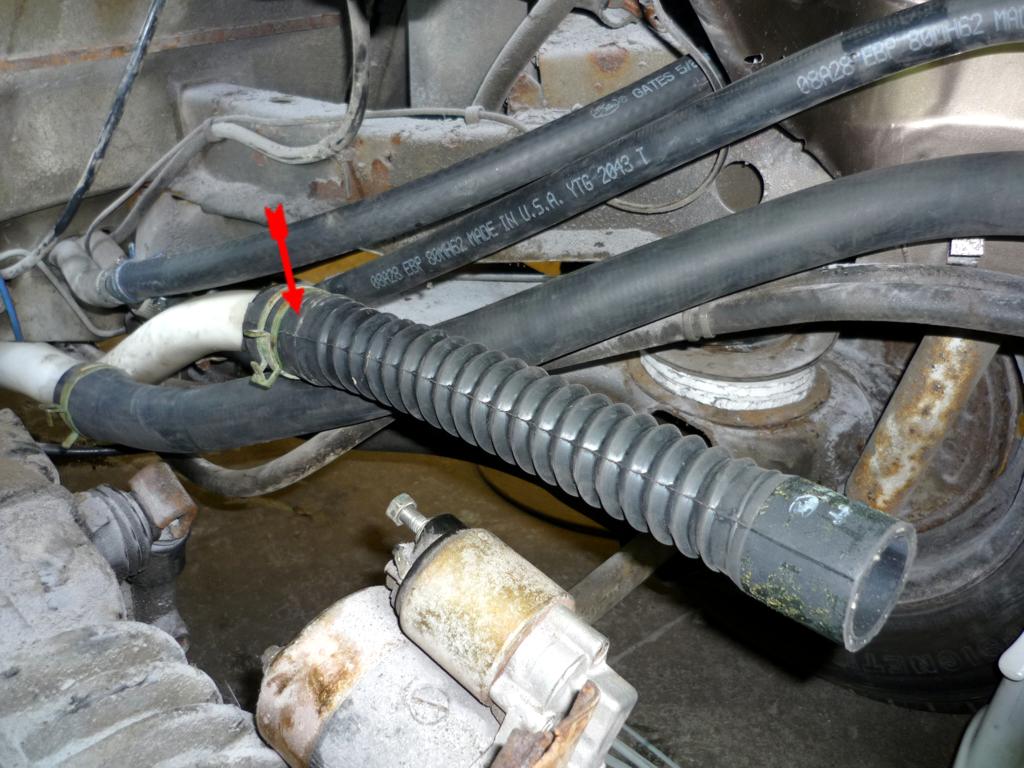
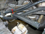
Installation of the main hot/outgoing coolant line from engine (later) to
white cooling pipe. |
Installation of the "S" hose. Hot coolant comming from reverse manifold and
going to EXP tank. |
   |
 |
 |
|
Installation du tuyau principale de retour du liquide refroidissant entre la
ligne principale de plastique blanche et le tuyau en métal. Plus gros en
diamètre du coté de la ligne de plastique blanche. |
Installation du
tuyau flexible accordéon. Liquide chaud provenant du moteur et allant
a la ligne de plastique blanche pour ensuite se rendre au radiateur. |
Installation du
tuyau en "S". Liquide chaud provenant du "Reverse Manifold" et allant au
réservoir d'expansion. |
|
|
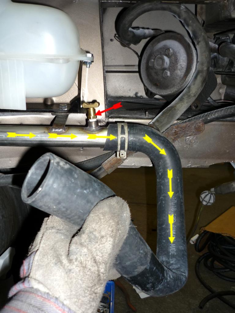
Installation of the hose between the metal (return coolant) tube to engine
thermostat. The red arrow show the bleeding screw. |
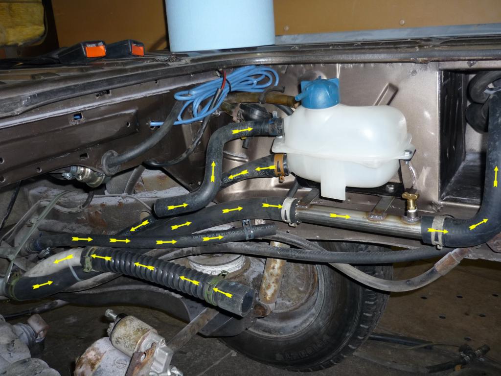
General view of the cooling system. The arrow show how the coolant flow. |
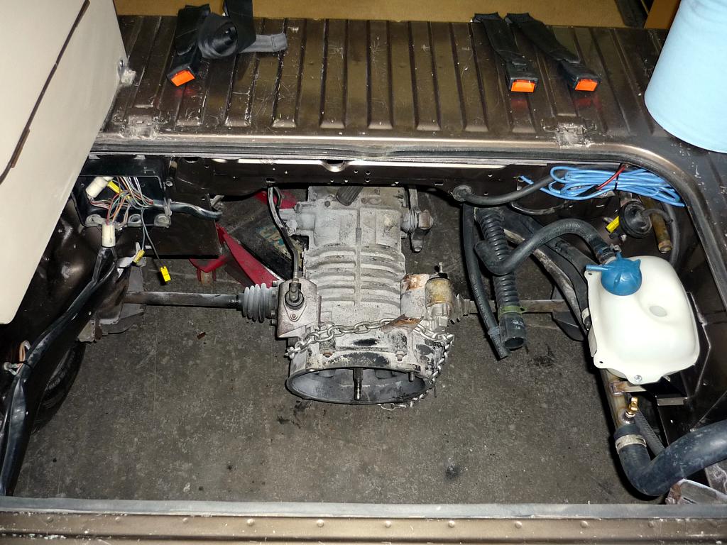
Ready to receive the engine |
|
|
 |
 |
 |
|
|
| Installation du
tuyau flexible situé entre le tuyau de metal (sous le réservoir) et le
thermostat housing du moteur (à venir) |
Vue générale du
système de refroidissement. Les flèches indique l'écoulement/la direction du
liquide. |
Pret a recevoir le
moteur |
|
|
|
| |
|
|
|
|